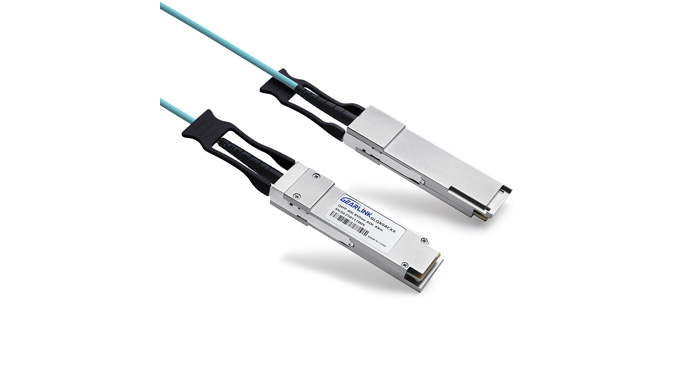
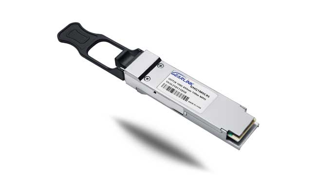
The QDD-400G-SR8 transceiver is a parallel 400Gb/s Quad Small Form Factor Pluggable--double density (QSFP-DD) optical module. It provides increased port density and total system cost savings. The QSFP-DD full- duplex optical module offers 8 independent transmit and receive channels, each capable of 53.125Gb/s operation for an aggregate data rate of 400Gb/s on 100 meters of OM3 multi-mode fiber.
An optical fiber cable with an MTP/MPO-16 connector can be plugged into the QSFP-DD SR8 module receptacle. Proper alignment is ensured by the guide pins inside the receptacle. The cable usually cannot be twisted for proper channel to channel alignment. Electrical connection is achieved through an QSFP-DD MSA-compliant edge type connector.
The central wavelengths of all the 8 parallel lanes are 850nm. It contains an optical MPO-16 connector for the optical interface and a 60-pin connector for the electrical interface. Host FEC is required to support up to 70m OM3 multi-mode fiber transmission.
The product is designed with form factor, optical/electrical connection and digital diagnostic interface according to the QSFP-DD Multi-Source Agreement (MSA) Type 2. It has been designed to meet the harshest external operating conditions including temperature, humidity and EMI interference.
The module incorporates 8 parallel channels, on 850nm Center Wavelength, operating at 50G per channel. The transmitter path incorporates an 8-channel CDR retimer, 2 sets of quad channel VCSEL drivers together with 2 sets of VCSEL arrays. On the receiver path, 2 sets of photo-diode arrays optics are coupled with an 8-channel CDR retimer. The electrical interface is compliant with IEEE 802.3bs and QSFP-DD MSA in the transmitting and receiving directions, and the optical interface is compliant to QSFP-DD MSA with MPO-16 Optical Connector. Figure 1 shows the functional block diagram of this product.
A single +3.3V power supply is required to power up this product. All the power supply pins are internally connected and should be applied concurrently. As per MSA specifications the module offers seven low speed hardware control pins (including the 2-wire serial interface): ModSelL, SCL, SDA, ResetL, InitMode, ModPrsL and IntL.
Module Select (ModSelL) is an input pin. When held low by the host, this product responds to 2-wire serial communication commands. The ModSelL allows the use of this product on a single 2-wire interface bus–individual ModSelL lines must be used.
Serial Clock (SCL) and Serial Data (SDA) are required for the 2-wire serial bus communication interface and enable the host to access the memory map.
The ResetL pin enables a complete reset, returning the settings to their default state, when a low level on the ResetL pin is held for longer than the minimum pulse length. During the execution of a reset the host shall disregard all status bits until it indicates a completion of the reset interrupt. The product indicates this by posting an IntL (Interrupt) signal with the Data_Not_Ready bit negated in the memory map. Note that on power up (including hot insertion) the module should post this completion of reset interrupt without requiring a reset.
Initialize Mode (InitMode) is an input signal. It is pulled up to Vcc in the QSFP-DD module. The InitMode signal allows the host to define whether the QSFP-DD module will initialize under host software control (InitMode asserted High) or module hardware control (InitMode deasserted Low). Under host software control, the module shall remain in Low Power Mode until software enables the transition to High Power Mode, as defined in the QSFP-DD Management Interface Specification. Under hardware control (InitMode de-asserted Low), the module may immediately transition to High Power Mode after the management interface is initialized. The host shall not change the state of this signal while the module is present. In legacy QSFP applications, this signal is named LPMode. See SFF-8679 for LPMode signal description.
Module Present (ModPrsL) is a signal local to the host board which, in the absence of a product, is normally pulled up to the host Vcc. When the product is inserted into the connector, it completes the path to ground through a resistor on the host board and asserts the signal. ModPrsL then indicates its present by setting ModPrsL to a "Low" state.
Interrupt (IntL) is an output pin. "Low" indicates a possible operational fault or a status critical to the host system. The host identifies the source of the interrupt using the 2-wire serial interface. The IntL pin is an open collector output and must be pulled to the Host Vcc voltage on the Host board.